R.H. Peterson G4-42 Manuel du propriétaire
Naviguer en ligne ou télécharger Manuel du propriétaire pour Foyers R.H. Peterson G4-42. R.H. Peterson G4-42 Owner`s manual Manuel d'utilisatio
- Page / 18
- Table des matières
- DEPANNAGE
- MARQUE LIVRES
- INSTALLATION & 1
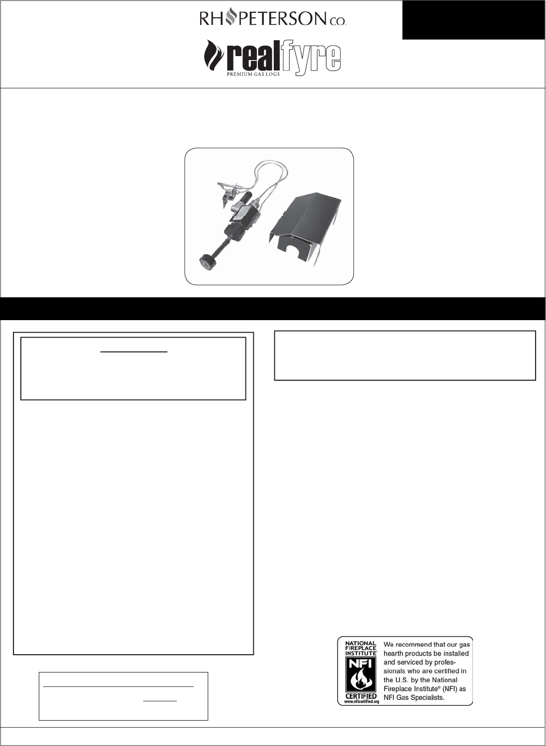
- OWNER’S MANUAL 1
- APK-17 PILOT KITS 1
- WARNING 1
- MODE D'EMPLOI 2
- APK-17 KITS DE PILOTES 2
- AVERTISSEMENT 2
- TABLE OF CONTENTS 3
- IMPORTANT INFORMATION 4
- SPECIFICATIONS 4
- REPLACEMENT PARTS LIST 5
- NOTES PAGE 6
- INSTALLATION 7
- INSTALLATION (Cont.) 10
- LIGHTING INSTRUCTIONS 11
- OFF PILOTE 12
- MANUAL LIGHTING 13
- ALLUMAGE MANUEL 14
- PILOT BURNER CHECK/ADJUSTMENT 15
- SHUTTING DOWN 15
- ORIENTATION 15
- FLAME HEIGHT 15
- VEILLEUSE CONTROLE/REGLAGE 16
- HAUTEUR DE LA FLAMME 16
- TROUBLESHOOTING 17
- WARRANTY 18
Résumé du contenu
1L-A2-256Rev 5 - 1310220810Important: Read these instructions carefully before starting installation of the burner control system.Robert H. Peterson C
10L-A2-256Rev 5 - 1310220810INSTALLATION (Cont.)CONNECT REMOTE RECEIVER (if equipped)1. Discard the black wires that come with the remote receiver. C
11PILOTOFFOFFONPILOTOFFONPILOTOFFONPILOTLIGHTING INSTRUCTIONS FOR YOUR SAFETY READ BEFORE LIGHTINGWARNING: If you do not follow these instructions ex
12PILOTOFFOFFONPILOTOFFONPILOTOFFONPILOTINSTRUCTIONS D'ALLUMAGE POUR VOTRE SÉCURITÉ LISEZ AVANT D'ALLUMERAVERTISSEMENT: Si vous ne suivez p
13LIGHTING INSTRUCTIONS (cont.)2. Locate the remote transmitter and press the ON/HI button (see Fig. 13-1). The ignition sequence will begin.Note:
14INSTRUCTIONS D'ALLUMAGE (cont.)2. Localisez la télécommande et appuyez sur le bouton ON/HI (voir Fig. 14-1). La séquence d'allumage comm
15LIGHTING INSTRUCTIONS (cont.)PILOT BURNER CHECK/ADJUSTMENTWith the pilot burner lit and the control knob in the pilot position, check the pilot sys
16INSTRUCTIONS D'ALLUMAGE (cont.)VEILLEUSE CONTROLE/REGLAGEAvec le brûleur de la veilleuse allumée et le bouton de commande dans le poste de pil
17TROUBLESHOOTINGPROBLEM CAUSE SOLUTION1. Pilot will not light a. Obstruction in pilot gas supply or pilot gas-supply line is kinkedb. Inadequate g
18Robert H. Peterson Co. • 14724 East Proctor Avenue • City of Industry, CA 91746 Quality Check Date:_________________Leak Test: ________________ Bu
2L-A2-256Rev 5 - 1310220810Important: Lire attentivement ces instructions avant de commencer l'installation du système de contrôle du brûleur.Rob
3L-A2-256Rev 5 - 1310220810TABLE OF CONTENTSGETTING STARTEDIMPORTANT INFORMATION ...
4L-A2-256Rev 5 - 1310220810CHECK TO BE SURE THAT THE PROPER FUEL GAS IS BEING USED WITH THIS PILOT KIT.The installation, including provisions for comb
5L-A2-256Rev 5 - 13102208104REPLACEMENT PARTS LIST26Note: Photos not to scale31Item Description Part No. Qty.1.orControl valve (natural)Co
6L-A2-256Rev 5 - 1310220810NOTES PAGEPlease use this page to record any information that you may want to have at hand.
7L-A2-256Rev 5 - 1310220810This safety pilot system must be installed by a qualifi ed professional service technician. Instructions must be followed ca
8L-A2-256Rev 5 - 1310220810FLAMEDIVERTERBRACKETBURNERPA N2 1/2REAR WALLBurner panFlame diverter bracket1-1/4"INSTALLATION (Cont.)INSTALL FLAME D
9L-A2-256Rev 5 - 1310220810INSTALLATION (Cont.)CONNECT TO GAS SUPPLYTo connect the valve to the gas supply, the fl ex connector kit and component parts
Produits connexes et manuels pour Foyers R.H. Peterson G4-42
 (14 pages)
 (16 pages)
 (28 pages)
© 2020, manymanuals.fr. Tous droits réservés | 0.801 s |
 Manymanuals.com
 Manymanuals.de
 Manymanuals.fr
 Manymanuals.it
 Manymanuals.pl
 Manymanuals.cz
 Manymanuals.es
 Manymanuals-pt.com
Commentaires sur ces manuels